Stone Security Engineering, PC will be 8 years-young on July 2nd, and what a wonderful 8-years it has been. I am so proud and excited about what we have accomplished. Among other things, we have
I look forward to the next 8 years to see what new mountains we can climb while continuing to provide customized and quality service for our clients and team members.
Thanks to all of you for being part of our family.
by Timothy Sisson, P.E.
Physical security requirements often include protection against a vehicle ramming threat, where an aggressor attempts to attack a facility by crashing a vehicle through the lobby or loading dock, or by breaching a controlled perimeter around the facility. These threats can be countered by anti-ram vehicle barriers, such as bollards, concrete planters, fences, and ditches/berms.
But how do you choose an anti-ram vehicle barrier? The answer is two-fold: 1) perform a vector analysis to determine the probable threat vehicle velocity at impact and 2) use published standards to specify a rating for the barrier.
A vector analysis requires the following:
The maximum acceleration of a vehicle typically ranges between 6 ft/s2 and 11 ft/s2. The acceleration may be increased if the attack route includes the vehicle going down a hill. The friction coefficient depends on road and tire conditions. It ranges between 0-to-1 with 0.6 typically used, however, using 1 is a conservative assumption.
The figure below shows a few examples of possible attack routes at access points around a controlled perimeter. In the figure, Attack Route 1 has a straight approach to the access point, while Attack Routes 2 and 3 are parallel to the access points and require the attacker to turn into the barrier before impact.
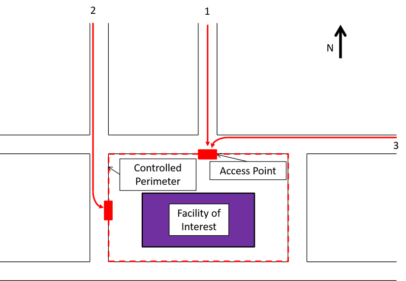
Attack Route 1 results in the highest impact velocity because the threat vehicle can continue to accelerate until impact. Attack Routes 2 and 3 limit the velocity at impact because the threat vehicle’s turning radius into the barrier is limited by the coefficient of friction between the tires and the road. If the turn is taken too quickly, the car will skid out of control.
Once the velocity at impact has been calculated, a barrier rating can be specified. At the moment, there are two primary standards used in the United States to rate anti-ram vehicle barriers: ASTM F2656 (F2656) and DoS SD-STD-02.01 (DoS). The DoS SD-STD-02.01 rating system is being phased out and to be replaced by ASTM F2656, but many existing anti-ram vehicle barriers have been tested and rated according to the DoS standard. Both standards rate barriers based on the weight of the vehicle, the velocity at impact, and the allowable penetration.
F2656 provides barrier ratings for multiple vehicle sizes ranging from sedans to heavy goods vehicles (e.g., dump trucks and semi-trailers), however, a common rating is for medium duty truck (M), which corresponds to the DoS “K” rating for a 15,000-lb vehicle weight. There are three (3) “M” ratings:
Which stands for a medium duty truck (M) with a velocity of 30, 40, and 50 mph at impact. These are equivalent to the DoS “K” ratings:
Which also represents a medium duty truck (15,000 lb) with a velocity of 30, 40, and 50 mph at impact.
The penetration rating is also similar between the two (2) documents. F2656 uses the following:
While the latest DoS rating system assumes a penetration of no greater than 1 M (i.e. a P1 in the ASTM system), previous versions used what was termed “L” ratings, as follows:
Obviously a barrier with a lower rating will cost less relative to a higher rated barrier. Performing a vector analysis may show that a K4 (or M30), rather than a K12 (M50), rated barrier is required. In addition, controlling the available attack routes can significantly reduce the barrier requirements by limiting the possible threat vehicle impact velocity. By thoughtfully approaching the rating requirements for anti-ram barriers, project costs can be managed so that the pool of available resources are used where they can best improve the safety and security of the facility and it’s occupants.
Strengthening a building to resist extreme loads (such as explosions, ballistics, and forced entry) that were not anticipated in the original design of the structure has a unique set of challenges and demands. These include not only the ability to resist the extreme load itself, but also constructability restrictions that come from trying to retrofit existing structures, the limitations of the existing materials and configurations, code requirements, and durability demands. Techniques and materials used to strengthen buildings and structures can generally be divided into two categories: Conventional and Innovative.
Conventional mitigation techniques and materials include structural element enlargement and the addition of supplemental supports using reinforced concrete and/or steel materials. These approaches have proven themselves to be effective solutions but they often pose constructability and compatibility challenges along with possible negative impacts from the added weight and loads on the existing building. These challenges can cause unanticipated time and cost implications for the retrofit project.
Innovative mitigation approaches and materials are alternative solutions to their conventional counterparts that can provide high strength-to-weight ratios, easier installation, resistance to complex threats and loads, and more effective dissipation of induced energy into the original structural systems. While we term these approaches ‘innovative’ they are not ‘shoot-from-the-hip’ solutions. They have been investigated and validated with testing and engineering modeling and are increasingly used to mitigate the challenges that conventional techniques and materials cannot adequately address. Examples of these materials include:
It is critical for the design engineer to understand the strengths and limitations of these innovative products and techniques, including the appropriate load ranges for the different threats and the required levels of protection. Implementation should be based on the published data and applicable guidelines and specifications.
As an example, externally applied composite materials such as Fiber Reinforced Polymers (often referred to as FRP) have proved to be effective in increasing the bending strength of masonry walls and concrete slabs, and with providing axial confinement improvement when wrapped around columns. However, this material has unique limitations and special considerations that must be understood and accounted for in the design to prevent pre-mature and possibly catastrophic failures.
These considerations include:
Overall, conventional or innovative materials and approaches have many potential applications in protecting people and property from extreme loads. However, their use requires a qualified engineer with a substantial understanding of mitigation approaches, dynamic behavior of the different types of materials, their physical properties, benefits and limitations in order to arrive at an effective and optimized mitigation solution.